Frequency-shift keying
FSK represents binary data by shifting a carrier between two predetermined frequencies: one for a logic 0 and another for a logic 1. Because the information sits in the frequency rather than the amplitude, FSK is relatively tolerant of amplitude noise and is used in modems, RFID and low-cost wireless links.
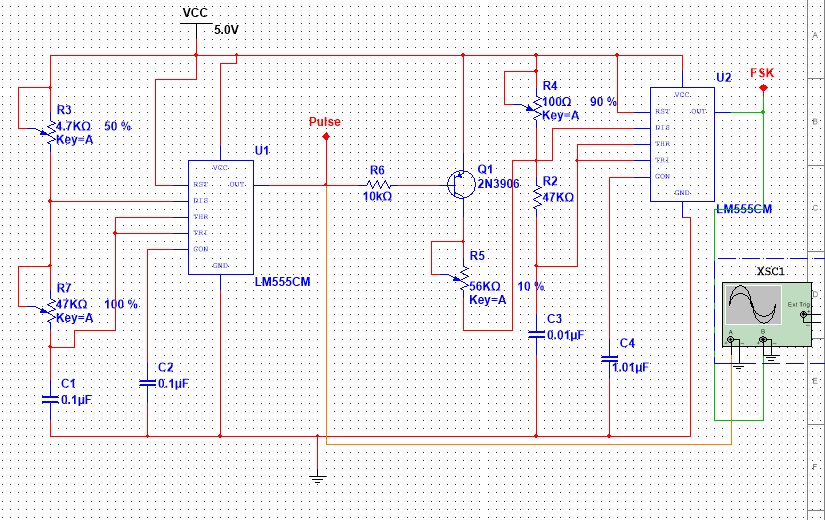
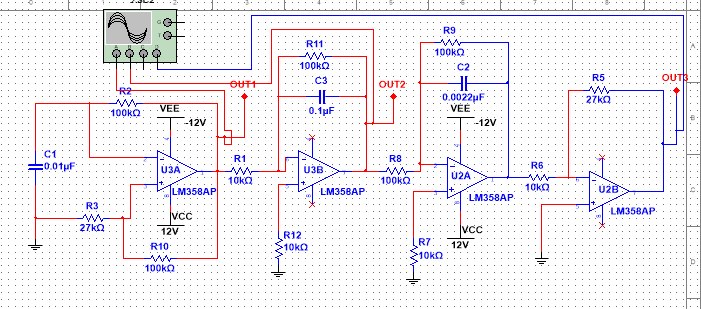
The study looks at the generator as a block: a digital input selects between two oscillator frequencies, and the output is a continuous carrier that changes frequency at the symbol boundaries. The important design parameters are the two carrier frequencies, the deviation between them and the data rate.
Function generator
A function generator produces the standard test waveforms: sine, square, triangle and sawtooth, with adjustable frequency and amplitude. The report compares the circuits used to generate each shape and the role they play in testing filters, amplifiers and communication stages.
The two topics belong together because both are about controlled signal generation. One produces a carrier that carries information; the other produces a known stimulus that lets you measure a circuit's response.
What the study covers
- The principle of FSK and where it is used in communication systems.
- Carrier selection, frequency deviation and data-rate trade-offs.
- Function-generator topologies for sine, square, triangle and sawtooth output.
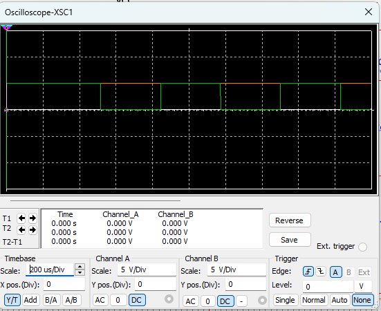
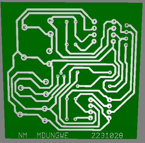
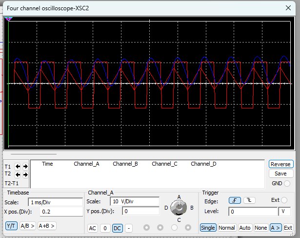
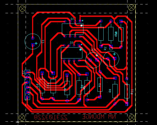
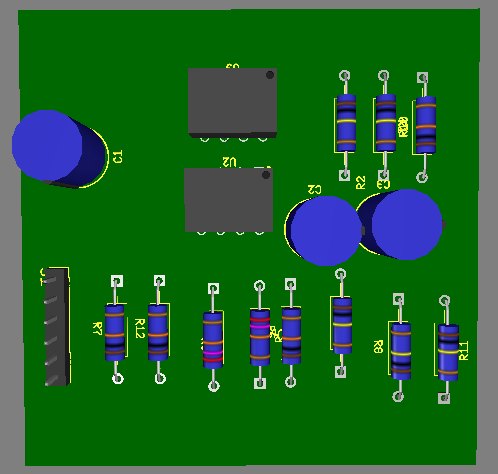
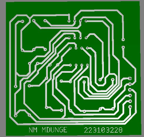
- Simulated circuit behaviour and the measurements used to verify it.
Reflection
This was a shorter lab study rather than a full build, and it is included because it shows the signal-generation side of the work: understanding what a waveform is made of before trying to measure or demodulate it. The next step would be to build the modulator and demodulator on a board and compare the recovered bit stream against the input at different noise levels.
Figures