The requirement
A security or convenience light should not run all day, and it should not switch on for every shadow. The brief was specific: sense ambient light with an LDR, detect people with a PIR sensor, and energise the output only when it is dark and motion has been observed. The supply is 10 V DC, and the board has to accommodate the SMT and through-hole parts listed in the project annexure.
How the two conditions combine
The LDR and a trimmer form a voltage divider. In daylight the LDR resistance is low, the divider holds the comparator in the state that keeps the output off, and the PIR signal is ignored. At dusk the LDR resistance rises, the comparator changes state, and the circuit is armed.
The PIR module produces a digital HIGH when it detects motion. That signal, gated by the darkness state, drives a transistor which switches the lamp or indicator LEDs. Both conditions have to be true at once, which is the whole point of the design.
Circuit blocks
- Light sensing: LDR and trimmer divider, with a PNP transistor providing a clean light/dark control signal.
- Motion sensing: PIR module on a three-pin header, with an NPN stage to shape the trigger.
- Decision: comparator with an adjustable reference so the dusk threshold can be calibrated on site.
- Output: NPN driver transistor switching the lamp, with indicator LEDs for bench testing.
PCB and test
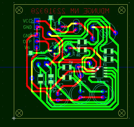
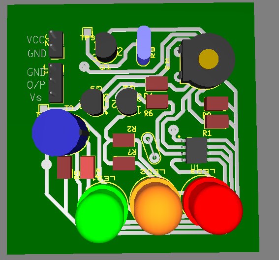
The circuit was captured and simulated in Multisim, then laid out in Ultiboard. SMT resistors and capacitors keep the board compact; the PIR sensor, LDR and trimmer are through-hole because they need to face the room and be adjustable after assembly.
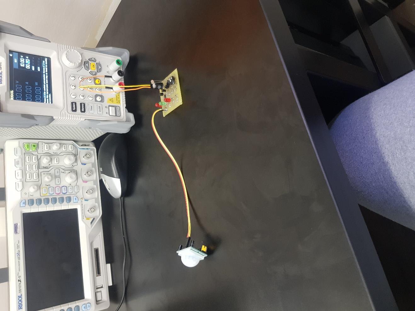
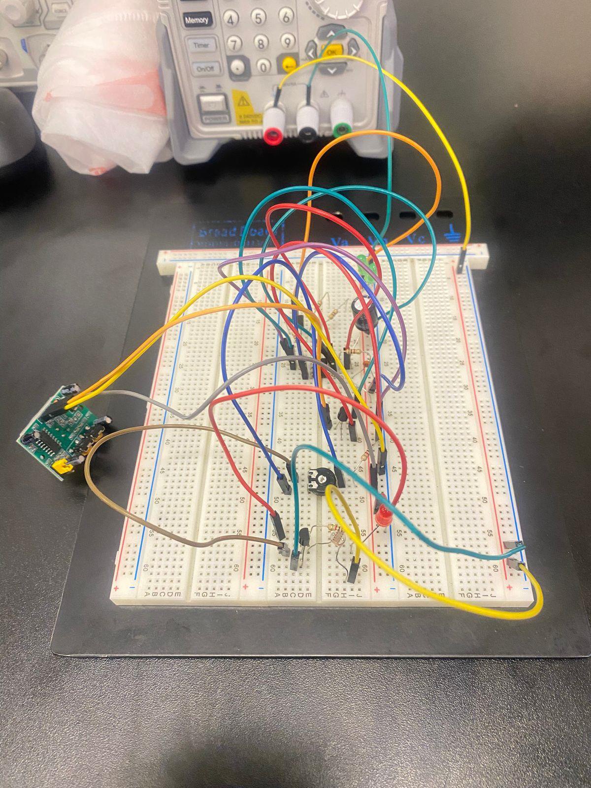
Simulation and prototype results were compared for the light-only, motion-only and dark-plus-motion cases. The final report records the three test conditions and the measured output states, along with the board layout and packaging. The remaining calibration point is the dusk threshold, which depends on where the sensor is mounted.
Figures