Why analogue
Distance sensing is usually a microcontroller with an ultrasonic or time-of-flight module. This project deliberately removes the microcontroller and asks how far the same job can be taken with parts that predate it: a 555 timer, an op-amp, comparators and a handful of passives.
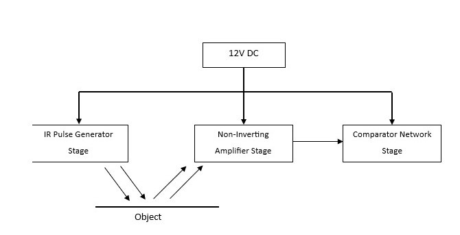
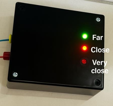
The answer is a three-state proximity sensor. An IR LED is pulsed, a photodiode receives the reflection, the weak signal is amplified, and comparator thresholds decide whether the target is close, at medium range or far. Three LEDs make the state visible without a display.
Transmitter and receiver
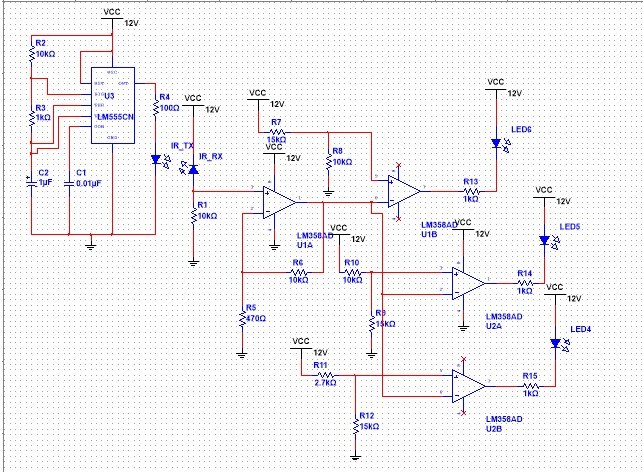
The 555 runs in astable mode and drives the IR LED at a carrier in the 12–40 kHz region. Pulsing the emitter rather than leaving it on makes the received signal easier to separate from ambient light and keeps the LED within its current rating.
The receiver is a photodiode feeding an LM358 non-inverting amplifier. Gain and offset are set so that a reflection from a nearby surface produces a usable swing without saturating on a white target. A second LM358 stage buffers the signal before the comparator bank.
Thresholds and output
Three comparators, each with its own resistor-divider reference, define the bands. The reference voltages were chosen from measured amplifier output at known distances, not from a textbook curve, because the reflection strength depends on the target surface as much as on distance.
The comparator outputs drive green, orange and red LEDs through current-limiting resistors. Only one LED is on at a time, so the display reads as a level rather than a bar graph, and the threshold spacing can be trimmed with the divider values.
Build and test
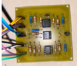
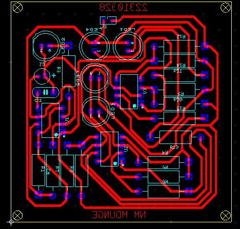
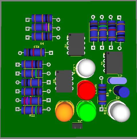
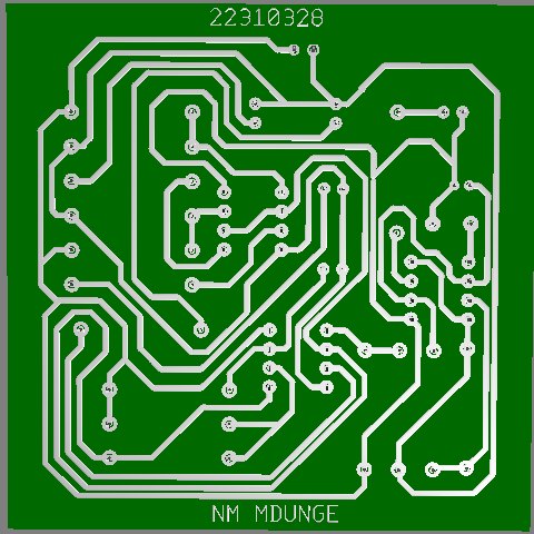
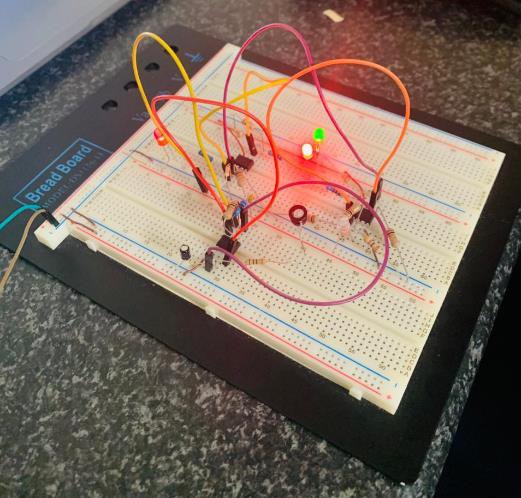
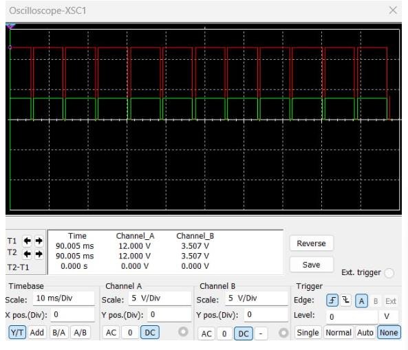
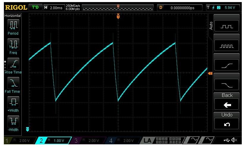
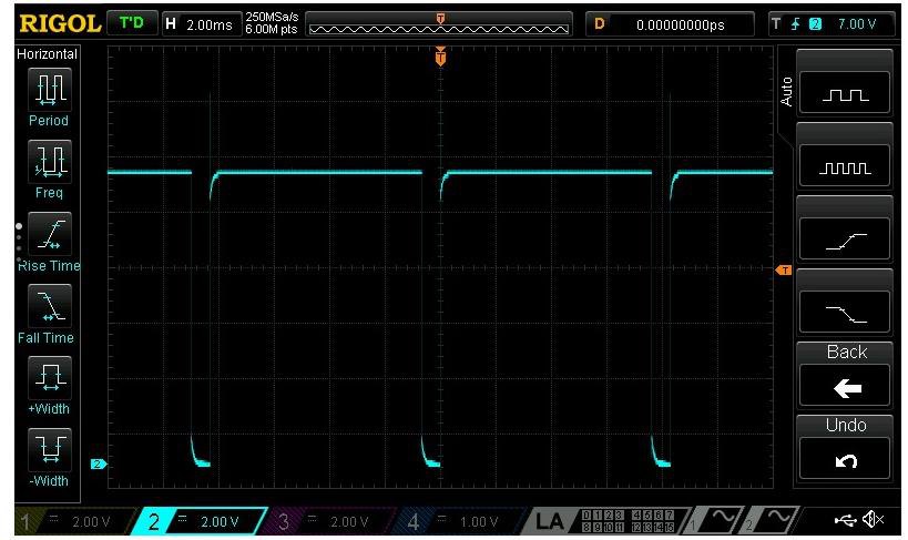
The circuit was simulated in Multisim, laid out on a PCB, assembled and tested against a wall at measured distances. Simulated and prototype waveforms were compared to check that the amplifier was not clipping and that the comparator edges landed where the design intended.
The final report documents the block diagram, PCB, packaging, simulated waveforms and prototype measurements. The main limitation is honest: reflected IR strength depends on surface colour and angle, so the sensor reports proximity bands rather than a calibrated distance in centimetres.
Figures